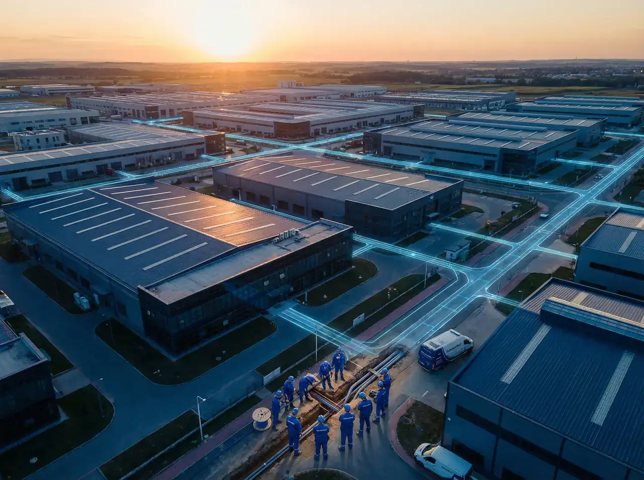
Overview Product Categories Application Scenarios Solutions Selection Guide Calculators Browse Products Partner CRM
Home Solutions Industrial Park Backbone
Solution 01

Industrial Park Backbone Optical Cable Solution

Unified scalable campus optical cable infrastructure for industrial, tech, and logistics parks — covering backbone, aggregation, and access layers with a complete fiber architecture.

Scenario Overview

Industrial parks, technology parks, and logistics parks typically cover areas ranging from tens of thousands to hundreds of thousands of square meters, with multiple buildings, multiple systems, and complex network structures. The optical cable infrastructure must simultaneously support video surveillance, access control, industrial monitoring, campus networks, and other systems.

The core challenge is not just "connecting" but building a unified, scalable, maintainable optical cable backbone that supports long-term operations and future expansion.

Key Engineering Challenge

Multi-building, multi-system, multi-layer architecture requires a unified backbone design that balances current needs with 10+ year lifecycle planning.

Industrial Park Backbone

Recommended Cable Types

Network Layer Recommended Cable Fiber Count Selection Rationale
Backbone Layer GYTA / GYTS / GYTA53 48F / 72F / 96F / 144F Inter-building trunk, high fiber count, armored protection, long-term reserve
Aggregation Layer GYTA / GYTS 24F / 36F / 48F Zone aggregation, duct installation, standard outdoor protection
Access Layer GYXTW / Central Tube 4F / 6F / 8F / 12F Camera aggregation, edge devices, flexible routing
Road Crossing GYTA53 / GYTS53 24F / 48F Direct burial armored, withstands vehicle load and soil pressure
Duct Installation

Installation Strategy

  • Backbone routes: Underground conduit system, GYTA/GYTS duct cable
  • Road crossings: GYTA53/GYTS53 direct burial armored cable, depth ≥1.2m
  • Aerial sections: Figure-8 or GYXTW self-supporting cable
  • Building entry: Transition to indoor cable at building boundary
  • Splice points: Outdoor splice closures at each building entry and aggregation point
  • Reserve conduit: Pre-install empty conduits for future expansion

Fiber Architecture Design

A three-layer star topology is recommended: Core Room → Zone Aggregation Points → Building Access Points. This structure provides clear fault isolation, easy maintenance, and supports future expansion without disrupting existing infrastructure.

  • Core room: Central fiber distribution frame (ODF), all backbone cables terminate here
  • Zone aggregation: Outdoor fiber distribution boxes (FDB) at each zone
  • Building access: Fiber termination boxes at each building entry
  • Reserve fibers: Minimum 30% spare capacity at backbone layer

Fiber Reserve Recommendation

For backbone routes that cannot be easily supplemented, we recommend selecting the next standard fiber count tier. For example, if current needs are 24F, deploy 48F; if 48F, deploy 96F.

Dual-Route Redundancy

For critical backbone links, consider dual-route deployment using different physical paths to eliminate single points of failure.

Supporting Equipment

  • Fiber Optic Distribution Frame (ODF) — Core room termination
  • Outdoor Fiber Distribution Box (FDB) — Zone aggregation points
  • Dome-type Splice Closure — Underground and direct burial splice points
  • Fiber Termination Box — Building entry points
  • SC/LC Fiber Patch Cords — Equipment room connections
  • OTDR — Acceptance testing and fault location
  • Fiber Fusion Splicer — Field splicing
  • Warning Tape & Marker Stakes — Underground route marking
  • Cable Labels & Asset Tags — Full route documentation
  • Conduit Sealing Materials — Building entry waterproofing

Ready to Plan Your Industrial Park Fiber Infrastructure?

Our technical team provides professional selection recommendations, BOM generation, and solution design support for your specific project requirements.